Best practices in decarbonisation for LNG export facilities
Reducing emissions from LNG plants can be technically feasible and economically viable as well as environmentally desirable
Recently, all business organisations have been under greater pressure from both the public and investors to manage their operations associated with reducing carbon footprints. As the US liquefied natural gas (LNG) market continues to grow due to globally increased demand for cleaner energy, reducing greenhouse gas (GHG) emissions from each stage of the LNG value chain has become particularly important to LNG project developers and facility owners.
Carbon dioxide (CO2) emissions associated with the liquefaction process account for approximately 6 to 10% of overall GHG emissions of the entire LNG value chain. Decarbonising current LNG export facilities is a difficult challenge for facility owners. Not only do they need to justify the increased cost associated with deploying various decarbonisation options, but they also must find those options that have demonstrated unmitigated success and can meet owners’ unique decarbonisation goals.
This article reviews some of the best practices in addressing decarbonisation for LNG export facilities from an engineering design point of view. Not all LNG projects are designed equally and with the same level of emissions. As a result, the authors believe there are opportunities for LNG facility owners to address the unique decarbonisation issues associated with their existing facilities, and for LNG project developers to do it right in the first place during the development of new projects.

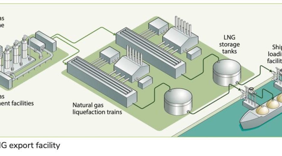
Process overview of LNG export facilities
An LNG export facility (see Figure 1) is typically comprised of natural gas treating facilities, one
or more liquefaction trains, LNG storage tanks,one or more LNG ship-loading facilities, as well as supporting infrastructure and utilities. In the natural gas liquefaction plant, LNG is produced from a cryogenic liquefaction process where natural gas (mainly methane) is cooled down to approximately -160oC (-256oF) at 103 kPa (15 psi)

to liquefy it for easy storage and transportation. The LNG production process flow is as follows: natural gas from raw gas transmission pipelines, typically at relatively high pressure, is fed to the LNG plant (see Figure 2), where it first goes through a series of processing steps to remove the undesirable components. These include heavy hydrocarbon liquids (condensate), free water, acid gases (carbon dioxide and hydrogen sulphide), water vapour, mercaptans, mercury, and other hydrocarbons heavier than methane called natural gas liquids (NGLs) contained in the natural gas feed stream, to prevent freezing issues in the cryogenic process, and to meet final LNG product specifications. Nitrogen, a potential natural gas contaminant, will be removed in the later cryogenic process through fractionation or fuel gas purge. After the NGLs are removed, the residual natural gas stream gets liquefied (using an external refrigeration system) and then sent to the end-flash nitrogen removal unit to meet the required specification to improve its calorific value and to avoid storage problems. The flash gas stream from nitrogen removal unit can be used as fuel gas. However, to meet fuel gas requirements, excess nitrogen needs to be rejected from this flash gas stream.
Emission sources in LNG export facilities
To understand the decarbonisation options in an LNG export facility, one must first locate the main GHG emission sources. There are primarily two major GHG emission sources in an LNG plant facility. One is CO2 and methane contained in the feed gas, and the other is the flue gas produced from fuel gas combustion devices, such as gas turbines, thermal oxidiser, and other process fired heaters.
CO2 in the feed gas is typically removed by amine absorption during feed gas treatment in the CO2 absorber in the acid gas removal unit (AGRU). The off-gas from the amine regeneration column, which typically contains CO2 and a small amount of hydrogen sulphide (H2S) and other light hydrocarbons, is sent to a thermal oxidiser to destroy the hydrocarbons and other hazardous components by combustion or oxidation. The thermal oxidiser is often operated with some augmented fuel gas due to the low heat value of CO2 off-gas from the AGRU. The flue gas from the oxidiser mainly contains nitrogen, unreacted oxygen, CO2, water vapour, nitrogen oxides (NOx), sulphur oxides (SOx), and tiny amounts of uncombusted hydrocarbons depending on the combustion efficiency of the burner. These components can be vented to the atmosphere (to the extent allowed by local regulations) at a safe location. Alternatively, a carbon capture unit for CO2 recovery can be added if needed.
The amount of flue gas produced from a gas turbine is proportional to its fuel gas consumption, which in turn is a function of the duty required (or power output), fuel gas composition, and thermal efficiency.
In addition, there are other emission sources in an LNG export facility. They can be intermittent or continuous and together can sometimes make significant contributions to the overall annual emissions of an LNG facility. Those emission sources include fugitive leaks from process equipment/turbomachines, piping and valves, vents from pressure control, compressor seals, emergency relief (flaring), and venting during commissioning, start-up, maintenance, and shutdowns. They may also include fuel gas purge for nitrogen removal (usually flared), nitrogen-rich venting from the nitrogen rejection unit, boil-off gas venting when boil-off gas compressor is down (usually flared), and ballasting vents during LNG storing and ship loading/unloading (also normally flared). Methane is a far more potent GHG than CO2, so flaring those emissions (rather than venting them) can reduce their impact by a factor of 35 or more.
Means to decarbonise LNG export facilities
While decarbonising an LNG export facility is a challenge, various efforts have been taken in the LNG sector to reduce emissions, which basically can be divided into the three following categories:
Elimination
This category represents the choice of energy forms that power an LNG facility which can eliminate GHG emissions.
Due to a proportional relationship between fossil energy or fossil fuel usage and GHG emissions, using a non-fossil fuel energy source will be the ultimate solution to achieve zero emissions. This includes using electrical motors based on electricity generated from renewable energy sources for refrigerant compressors. While partial substitution of fossil fuel by non-fossil fuel is possible for an LNG facility, with current technologies and energy mix, completely substituting fossil fuel is unlikely. It is particularly challenging for those existing LNG facilities that have already installed gas turbines for their refrigerant compressors.
Mitigation
On the basis of utilising fossil fuel energy, decarbonisation means reducing emissions from fuel gas combustion or methane leaks from piping and instrument leaks. This category includes improving energy efficiency through process design and equipment modifications. This includes utilising more energy-efficient equipment and advanced technologies associated with minimising emissions. It should be noted that, even if all of these mitigation methods are applied, not all GHG emissions associated with operating the facility may be eliminated.
Sequestration
The amount of CO2 in the feed gas and the turbine exhaust gas will be released into the atmosphere if it is not captured and stored. Carbon capture and sequestration (CCS) is considered a must-deploy technology to achieve net-zero emissions by 2050. CCS for LNG plants includes efforts that utilise commercially available CCS technologies to capture and sequester CO2 emissions, mainly from the AGRU and the gas turbine exhaust.
Examples of decarbonisation practices:
Improvement of energy efficiency
The energy efficiency for an LNG plant is generally defined as energy input or requirement to produce a unit mass of LNG, such as kWh/kg or kWh per metric ton (MT). Each metric ton of LNG produced is estimated to require approximately 170 to 350 kWh of energy. In the absence of utilising renewable power from the grid, about 8 to 12% of feed gas is needed to produce power to run an LNG plant (including the fuel gas needed for gas turbines that drive refrigerant compressors). This is equivalent to GHG emissions of approximately 0.16 tCO2e/tLNG to 0.48 tCO2e/tLNG. For
given feed gas conditions (such as pressure, temperature, and compositions), site conditions, and liquefaction technology selected, those values are strongly dependent on the type of drivers used for refrigeration compressors and the level of energy and heat integration.
Driver type
Efficiency of drivers varies with type. Heavy-duty frame turbines typically have an energy efficiency of 33 to 35%. For aero- derivative turbines, the energy efficiency ranges from 41 to 44%. The energy efficiency of a combined cycle gas turbine (CCGT) can run up to an energy efficiency of 60%. Recently, electrical motors with zero emissions (if the electricity is from a renewable source) have increased interest. Electric drive has been proposed for new LNG facilities that are geographically located where it is feasible to use renewable power from the grid.
Heat recovery and integration
For LNG plants that use gas turbines, recovering heat from turbine exhaust gas has become a standard design. The recovered waste heat can be used as a heat source for process use, such as providing heat for molecular sieve dehydration regeneration gas and heating medium. This can eliminate the use of dedicated fired heaters, which means no fuel gas consumption and no emissions for these necessary utilities.
Energy recovery
In several areas of an LNG plant, high-pressure fluids are sometimes let down to lower pressure for process reasons. For instance, in the feed gas circuit, the high pressure of feed gas is often let down to a lower pressure as required for NGL recovery. And in the rich amine circuit, the high-pressure, rich amine stream exiting from the bottom of a high- pressure amine absorber is typically let down to a lower pressure for amine flashing. In those instances, pressure letdowns are commonly realised by throttling valves. An alternative is to use turbine/expanders and turbochargers, respectively, to recover some of the lost energy. Note that the cost of equipment and maintenance of said equipment is not trivial and must be considered in the overall analysis.
Mitigation of emissions
In addition to improvement in energy efficiency, there are other areas where decarbonisation opportunities exist in a liquefaction export facility. Many have been successfully practised in operating LNG facilities and are accepted as standard features, designs, or procedures. The following is a short list:
Fugitive emissions prevention
Prevention of hydrocarbon leaks from static equipment and turbomachines, piping connections and valves, plus associated safety and environmental regulation compliance are ongoing tasks of LNG facilities during design and operations. A good fugitive emission management programme should address quantifying and eliminating fugitive emissions in the first place, i.e., during the design phase. This includes compressor type selection (including seal type) and valve selection (i.e., low [external] leakage valves versus high leakage valves).
Abnormal venting and emergency relief
Emissions through venting/flaring during emergency shutdowns can sometimes be enormous. Implementing predictive maintenance programmes and improving equipment reliability can help prevent unplanned shutdowns and thus reduce lifetime emissions from the facility.
Overpressure protection
Overpressure protection through relief and depressurisation systems in LNG process facilities is the standard means of protecting people, an owner’s assets, and the environment. However, in reviewing emission- mitigating methods for overpressure protection, atmospheric release (usually via flaring) and the associated negative environmental impact, as well as the potential lost revenue due to relief valve opening, must be addressed. It is common practice to consider solutions such as inherent safer design through high-integrated pressure protection systems (HIPPS) that can address both potentially hazardous emissions and the costly release while still providing overpressure protection.
Commissioning and start-up
Venting during process commissioning and start-up is unavoidable. However, emissions can be mitigated through proper planning and reviewing of commissioning and start-up procedures. For instance, utilising nitrogen for initial dry-out of mercury removal beds (placed downstream of the dehydration vessels) may have advantages over using fuel gas in minimising CO2 emissions. Similarly, during AGRU commissioning, or turndown operation at start-up, the over- circulating lean amine may be unnecessary
as it will increase the amount of dissolved hydrocarbons in the rich amine and potentially increase emissions, depending on the disposition of the flash gas.
Carbon capture and storage
Chevron Australia’s Gorgon LNG facility installed the world’s largest CCS system to capture carbon emissions. After treatment, CO2 captured from the AGRU in the feed gas pretreatment section of the LNG plant is injected into a giant sandstone formation about 2000 meters deep from the surface, where it remains permanently trapped.